
Independent CFD
Targeted scouring versus conventional bottom plenum
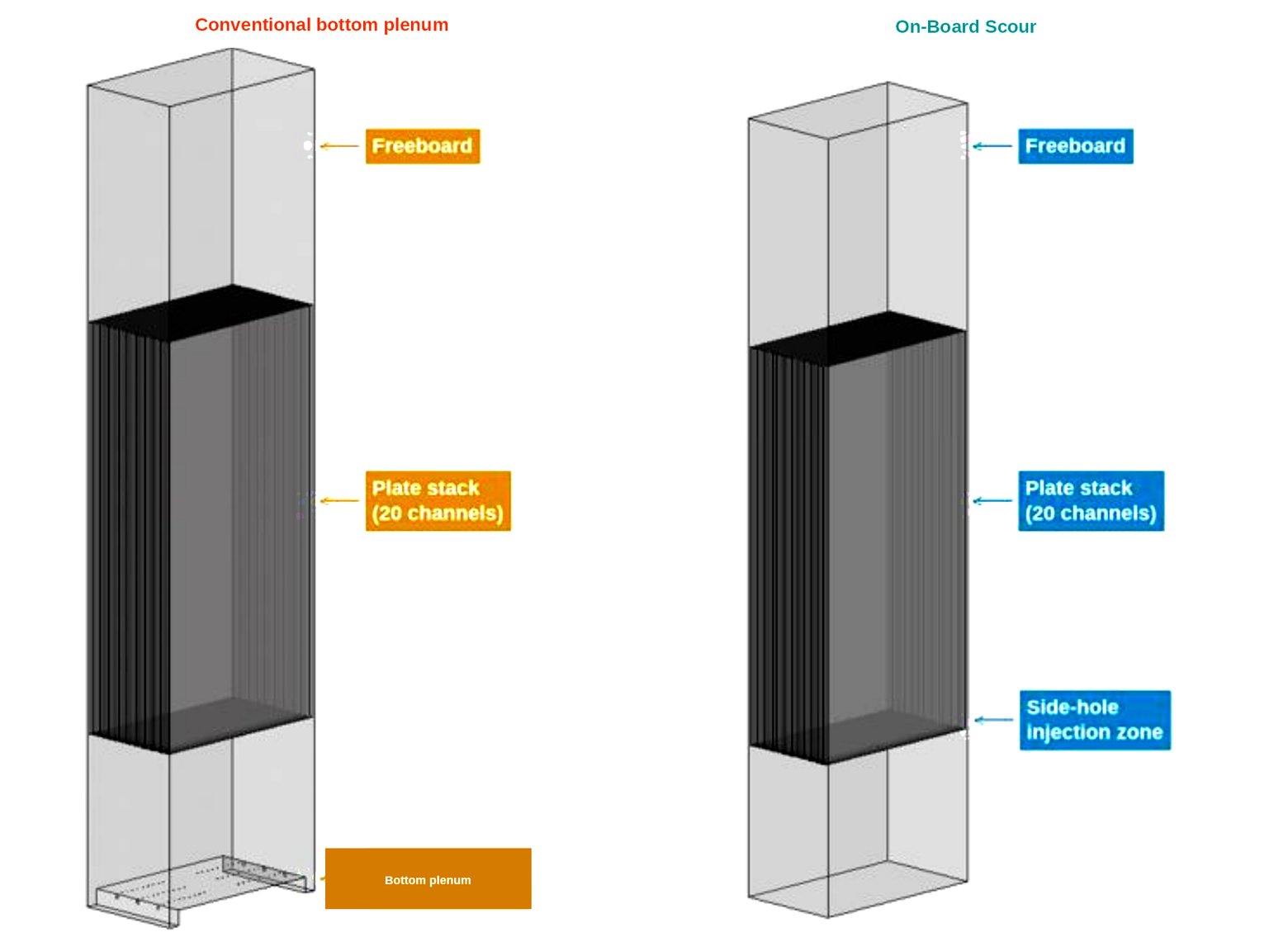
Targeted scouring uses a detachable modular scour manifold. It attaches to the bottom of the plate. Check valves keep sludge and mixed liquor out of the air path. Dedicated scour, 24/7, at the root of every channel. A conventional bottom plenum shares one chamber under the stack and lets buoyancy sort the rest. Independent CFD stills of the two on identical plates.
Hydrodynamics only — fouling, flux, biology, and long-term operation are outside the scope. These are independent CFD predictions under the stated modeling assumptions. They are not plant data.
The CFD was run on a 20-channel section. The shipped module is 130 plates (single-deck, ≈136.5 m2) or 260 plates (double-deck, ≈273 m2). Figures of 20 panels, ≈21 m2, and 200 L/min described that modeled section only.
What operators see
A mix of scoured and starved channels
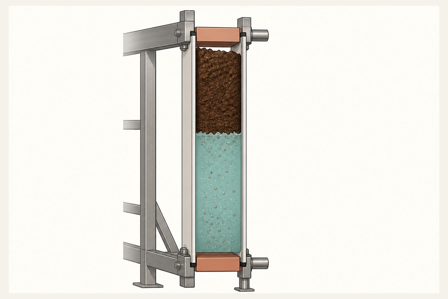
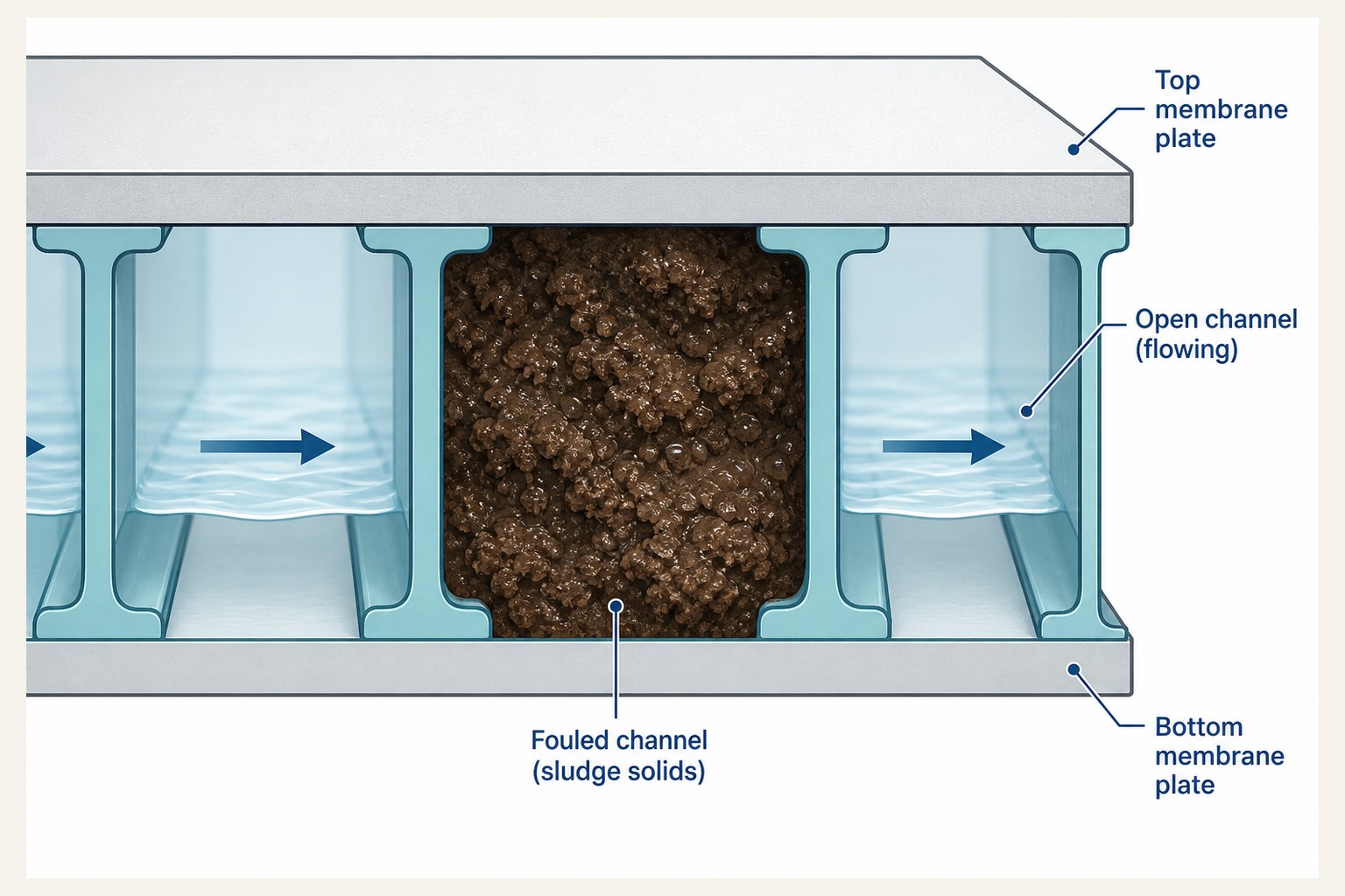
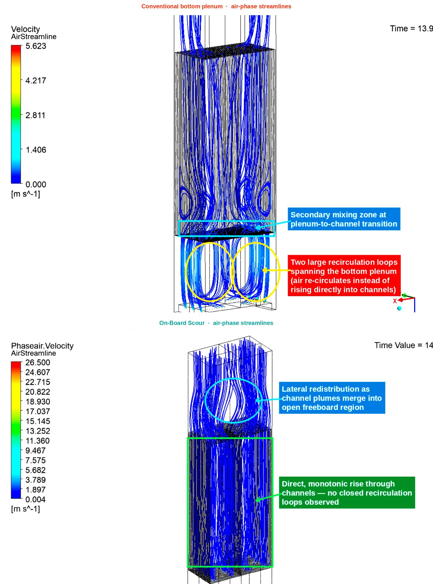
A conventional bottom plenum recirculates. Buoyancy sorts the rest. Some channels run strongly scoured. Neighbors starve. Sludge packs at the top of a starved channel. The plates next to it can still flow. Liquor under the plates can stay mixed. From the walkway the tank looks fine.
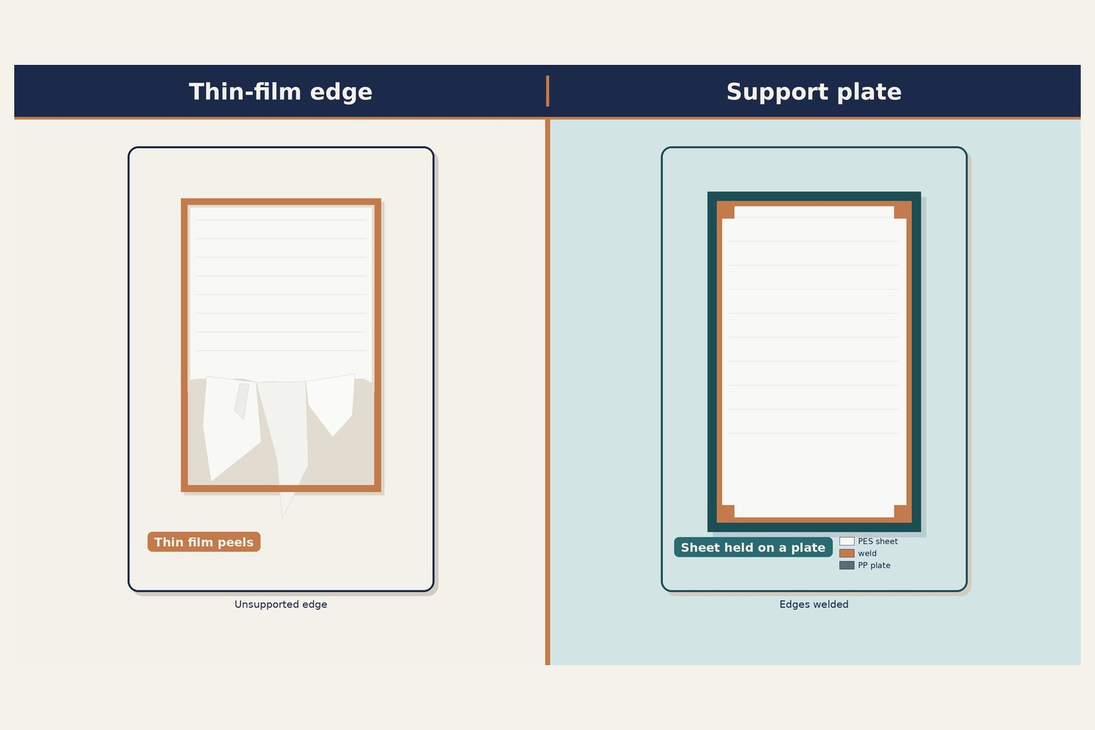
Thin-film sheets peel and fray. There is no support plate behind them. Hair wraps a hollow fiber — that is a geometry point, not a brand. Early clogging, broken fibers, and a membrane change in three to five years are familiar in this field. The current state of the art is not finished. We have to do better.
What the study compared
| Conventional | Three-header bottom-plenum air scour. Shared chamber under the stack. |
|---|---|
| Targeted scouring | Detachable modular scour manifold on the bottom of the plate. Direct injection at the base of each channel. No bottom plenum. |
| Modeled section | 20 channels (not the shipped module). Plate 1,047 × 502 × 7.60 mm, 6.40 mm channel gap. Identical in both cases. |
| Domain | Bi-symmetric quarter-domain. About ten of twenty channels genuinely resolved. |
The conventional case is a conventional-style geometry on Zyramic’s own plate. It is not a named competitor’s product.
ZX · whole plate
One starved face. One well-fed neighbor.
Same conventional bottom plenum. Same stack. Two channels, two ZX faces. One is almost empty. The neighbor is well fed. That is the mix operators see in the tank — and the reason sludge can pack at the top of one channel while the next one still flows.
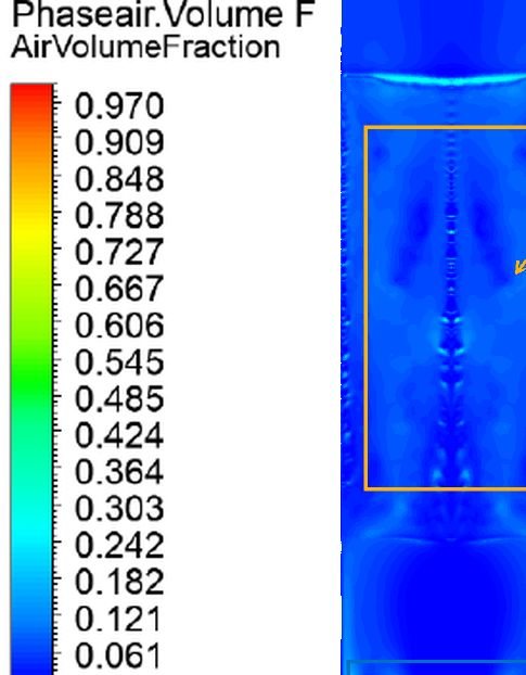
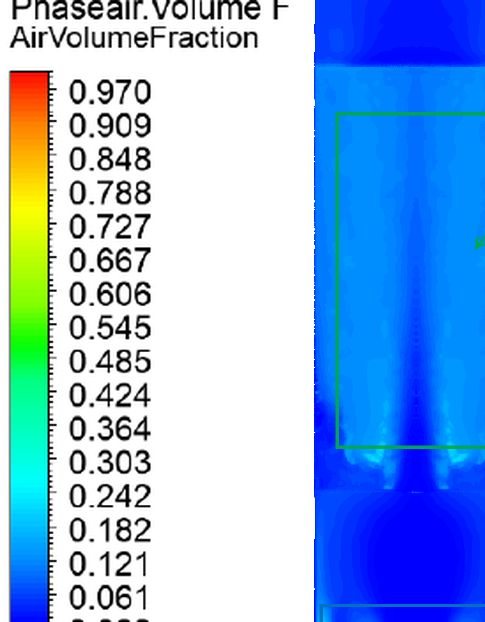
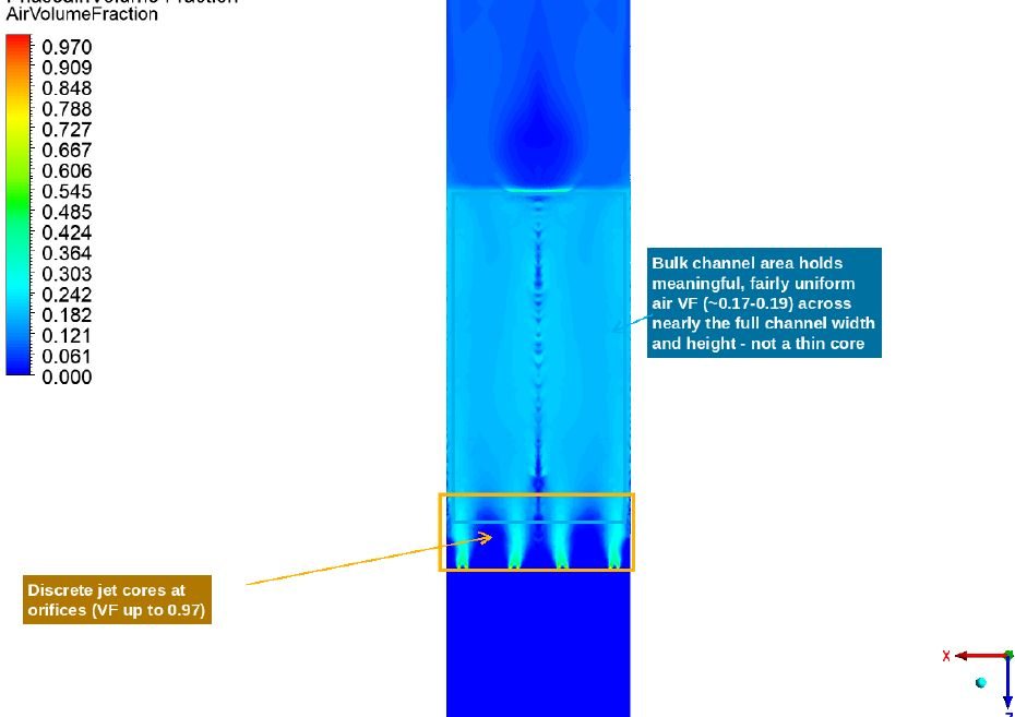
Targeted scouring puts dedicated injection at the root of every channel. The ZX face shows holdup across the plate — not a thin core, not a starved neighbor.
Where scouring begins
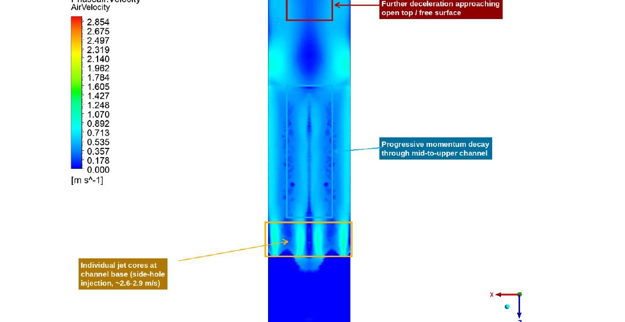
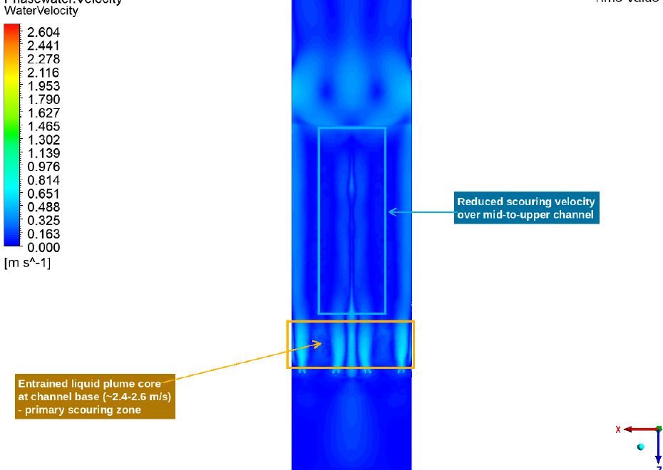
Near-field water velocity at the channel base — the liquid shear where scouring starts — was 2.4–2.6 m/s with targeted scouring versus 0.5–0.75 m/s in the bottom plenum. That is about four times the liquid shear at that location. It is not a claim of four-times scouring over the whole panel. In-channel peaks farther up the plate are similar in both designs, on the order of 0.7–0.9 m/s.
Direct rise through every channel
Channel to channel
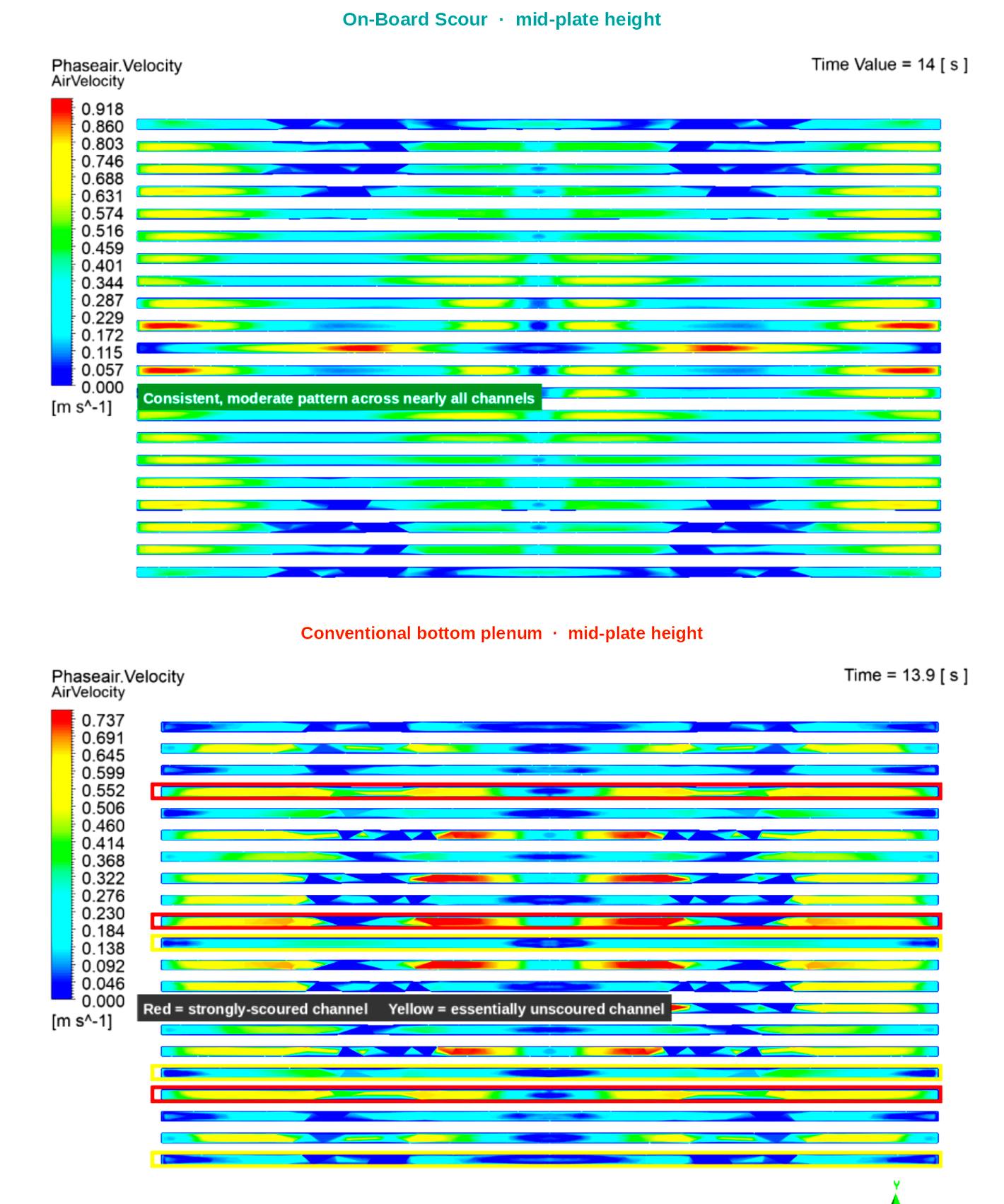
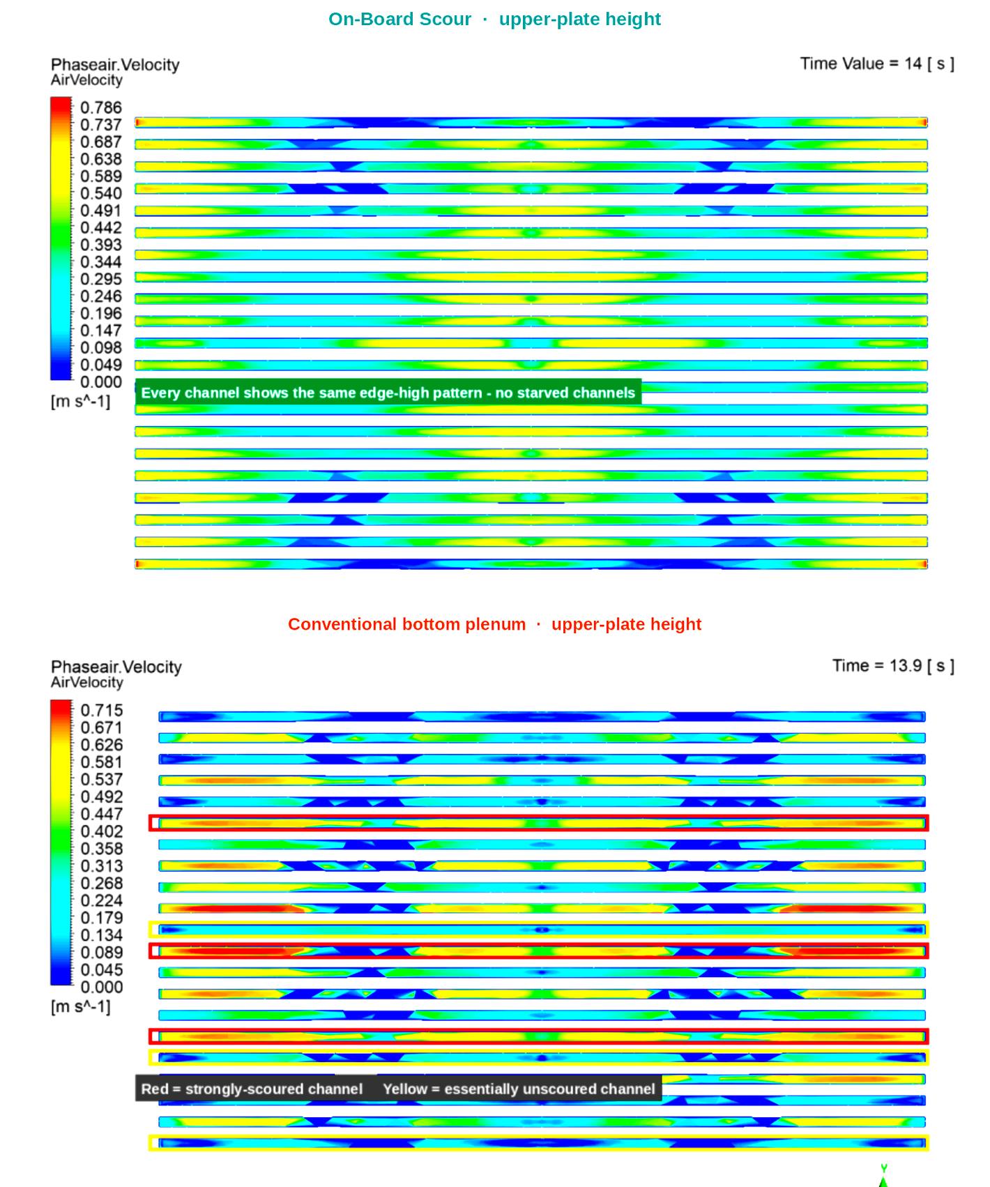
Same cross-section, two heights. The mid-plate and upper-plate heat maps look down the identical channel array. Targeted scouring stays even in every channel at both heights. The conventional bottom plenum shows strongly-scoured channels next to starved ones, and that mix persists toward the top of the panel.
The uniformity finding and the near-field shear finding are separate. Together they show even scour in every channel, and a strong start at the plate base. This is an interleaved starved-versus-scoured pattern — not a sides-versus-center rack story.
The plate
Support plate. Detachable manifold. Check valves.
The polypropylene support plate holds the PES sheet. Targeted scouring uses a detachable modular scour manifold. It attaches to the bottom of the plate. Check valves keep sludge and mixed liquor out of the air path. Dedicated scour, 24/7, every plate. Secure in the tank. Change on the bench.

Shared limits, not differentiators
- Both designs show an edge-high, centre-low pattern across the 502 mm panel width (riser/downcomer in the enclosed channel).
- Both show decay of scouring velocity over the upper portion of the 1,047 mm panel. Zyramic’s response is a shorter panel, not a claim that the decay is absent.
What this study does not show
- Lower fouling, higher flux, longer membrane life, or less blower energy in the field.
- Physical or plant validation. None has been done against this model.
- Full-rack header or manifold asymmetry. The quarter-domain cannot confirm it.
Independent FEA
Independent FEA covers the module in operation and in lift-out. Worst case included: wetted, double-deck. Predictions under the stated modeling assumptions. Not plant data. No report download.
Datasheet, O&M, and warranty are on Downloads.
Questions people ask
Straight answers
How does targeted scouring compare with a conventional bottom plenum?
An independent CFD study compared the two on identical plate geometry. Targeted scouring feeds every channel. A conventional bottom plenum leaves a mix of strongly scoured and starved channels. Near-field liquid shear at the channel base was about four times higher with targeted scouring. Hydrodynamics, not plant data.
What did the independent FEA cover?
The module in operation and in lift-out. Worst case included: wetted, double-deck. Predictions under the stated modeling assumptions. Not plant data. No report download.
Is this plant performance data?
No. Independent CFD and FEA figures are predictions, not plant data. Zyramic does not invent a kWh, a percent energy, or a plant TMP curve.